MissionSpacecraft / Instruments
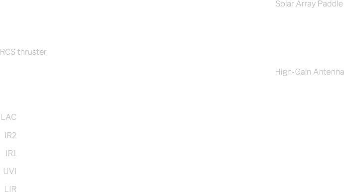
Akatsuki is a spacecraft shaped like a box (1.04 m x 1.45 m x 1.40 m) equipped with two solar array paddles. It is equipped with thrusters and antennae that respectively allow it to enter orbit, to change attitude and to communicate with the Earth.
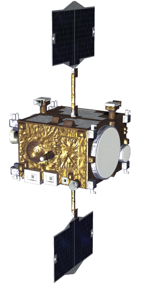
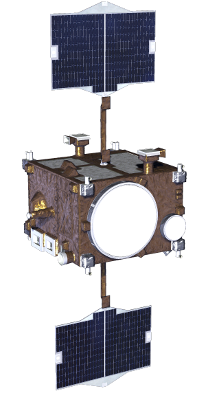
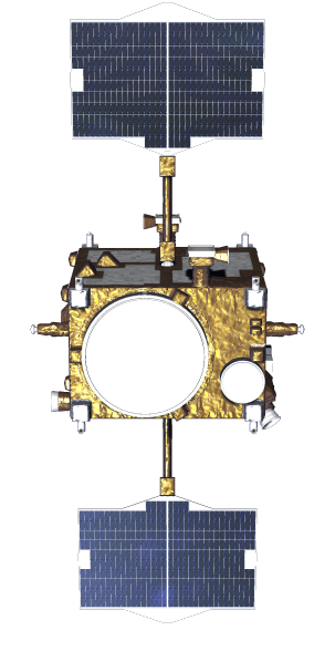
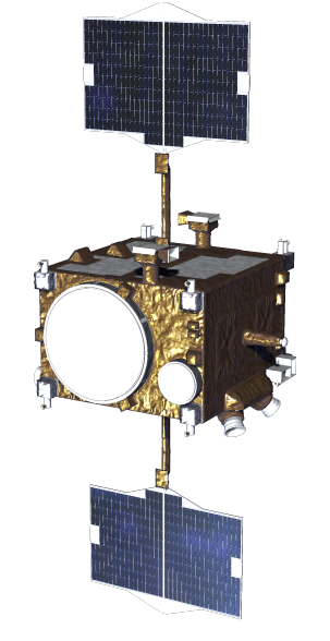
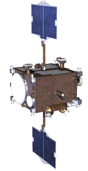
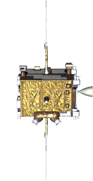
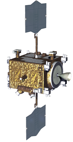
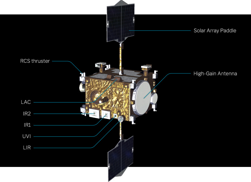
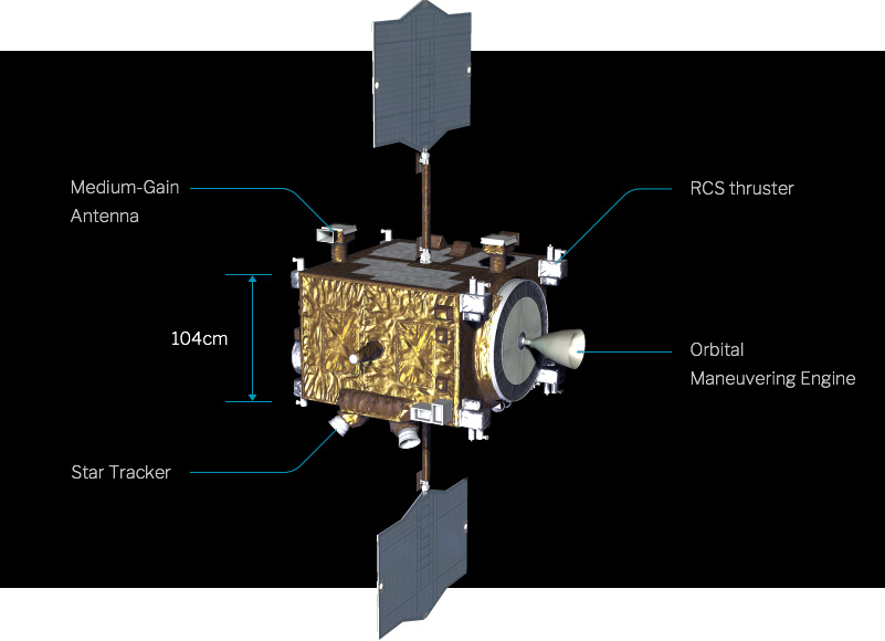
Venus is closer to the Sun than the Earth, so it is subject to strong sunlight. The two surfaces perpendicular to the booms of the solar array paddles are not exposed to sunlight, with silver radiating material being used to dispose heat into space. The remaining surfaces are covered with gold color insulating material to protect the spacecraft's internals from the effects of increased temperature due to sunlight. The antenna used to send observational data to the Earth is a flat-surface antenna, which prevents sunlight from being collected on it and raising the temperature. The main spacecraft body does not rotate, with the solar array paddles always pointing towards the Sun and allowing for a stable power supply.
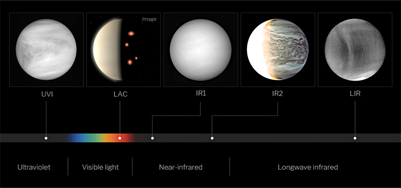
As an observatory satellite orbiting Venus, Akatsuki consists of five cameras that allow for obtaining images of Venusian atmosphere at various wavelengths between ultraviolet and long-wave infrared, as well as an ultra-stable oscillator used to measure vertical profiles of temperature, pressure, and so on. The five cameras are all installed facing the same orientation so as to enable simultaneous observation of Venusian atmosphere.
Wavelengths observed by Akatsuki
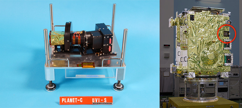
Ultraviolet imager (UVI)
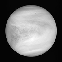
UVI acquires ultraviolet images, allowing us to obtain the distribution of sulfur dioxide, which is related to the cloud formation, and the distribution of unidentified chemical substances which absorbs the ultraviolet rays. Also, we can measure the wind speed at the cloud tops by tracing the dark-and-light pattern due to the scattering of ultraviolet rays in sunlight by Venusian clouds.
PI: Shigeto Watanabe (Hokkaido Information University)
Specification
| Mass | About 4.1 kg |
|---|---|
| Field of View | 12° x 12° |
| Detector | Si-CCD (1024 x 1024 pixels) |
| Wavelength and Target | 283 nm (dayside: sulfur dioxide at cloud top) 365 nm (dayside: unidentified absorbent substances) |
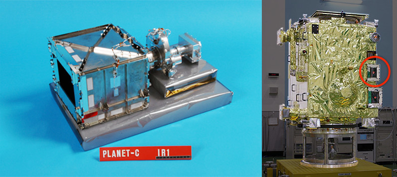
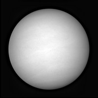
1 µm camera (IR1)
By utilizing the wavelength bands around 1 µm, which allows for seeing below clouds and near the surface of Venus, and by comparing infrared intensities of different bands, we can investigate the movement of clouds in the lower atmosphere, the distribution of water vapor, the mineral composition of the surface, and can check for the presence of active volcanoes.
PI: Naomoto Iwagami (former University of Tokyo)
Camera equipment data
| Mass | About 6.7 kg* |
|---|---|
| Field of View | 12° x 12° |
| Detector | Si-CSD/CCD (1024 x 1024 pixels) |
| Wavelength and Target | 1.01 µm (nightside: ground surface and clouds) 0.97 µm (nightside: water vapor) 0.90 µm (nightside: ground surface and clouds) 0.90 µm (dayside: clouds) |
*Includes common circuitry shared with IR2 (about 3.9 kg)
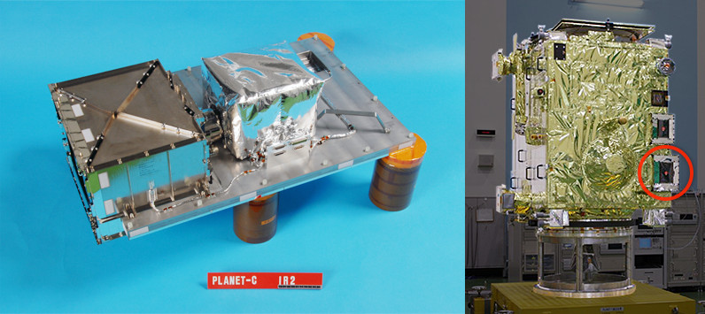
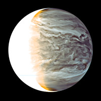
2 µm camera (IR2)
The 2-µm wavelength, which is emitted from below the bottom of Venus' clouds, allows for observing their density, the size of the cloud particles, the distribution of carbon monoxide, and other parameters, allowing for insights into atmospheric circulations at lower altitudes and into how clouds are formed. Zodiacal light was also measured en route to Venus to investigate on the dust distributed in the solar system.
PI: Takehiko Satoh (ISAS/JAXA)
Specification
| Mass | About 18 kg* |
|---|---|
| Field of View | 12° x 12° |
| Detector | PtSi-CSD/CCD (1024 x 1024 pixels) |
| Wavelength and Target | 1.735 µm (nightside: cloud and particle size distribution) 2.26 µm (nightside: cloud and particle size distribution) 2.32 µm (nightside: carbon monoxide) 2.02 µm (dayside: cloud top altitude) 1.65 µm (zodiacal light) |
*Includes cryocooler and common circuitry shared with IR1 (about 3.9 kg)
Long-wave infrared camera (LIR)
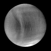
Infrared radiation of 10-µm wavelength is used to measure the temperature at the cloud tops. Two-dimensional temperature distribution at cloud tops can be used to investigate various types of waves and convection within the upper cloud layer, as well as wind speed distribution on the upper cloud tops of both dayside and nightside.
PI: Makoto Taguchi (Rikkyo University)
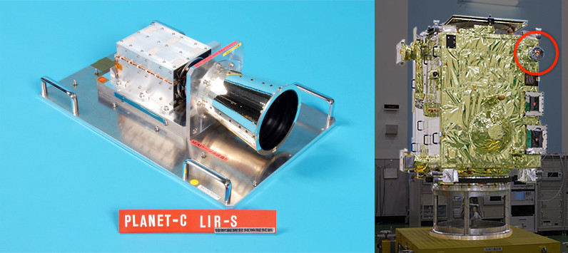
Specification
| Mass | About 3.3 kg |
|---|---|
| Field of View | 16° x 12° |
| Sensor | uncooled micro bolometer array (328 x 248 pixels) |
| Wavelength and Target | 10 µm (dayside/nightside: cloud top temperature) |
Lightning and airglow camera (LAC)
This camera, which can capture brightness changes at 1/30,000 of a second, detect lightning discharge at small intervals and can be used to settle the controversy on the occurrence of lightning in the Venusian atmosphere. In addition, it captures airglow produced by oxygen in the higher atmosphere at around 100 km, allowing for visualizing atmospheric circulations and waves between dayside and nightside.
PI: Yukihiro Takahashi (Hokkaido University)
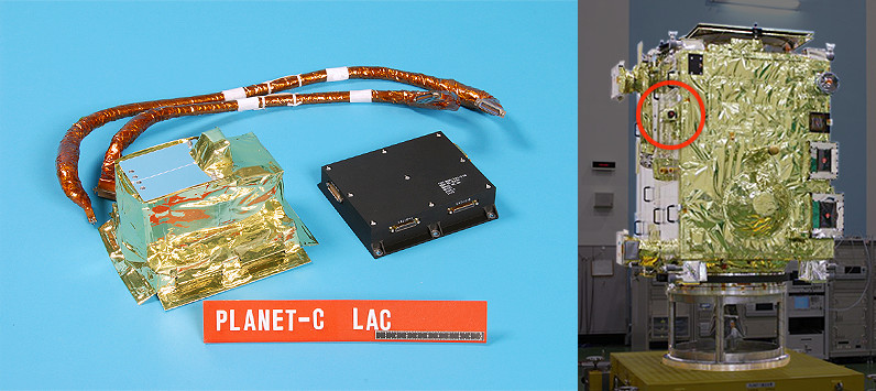
Camera equipment data
| Mass | About 2.3 kg |
|---|---|
| Field of View | 16° x 16° |
| Detector | 8 x 8 APD matrix array |
| Wavelength and Target | 777.4 nm (nightside: lightning discharge) 480 - 605 nm (nightside: airglow from oxygen molecules) 557.7 nm (nightside: airglow from oxygen atoms) 545 nm (for calibration use) |
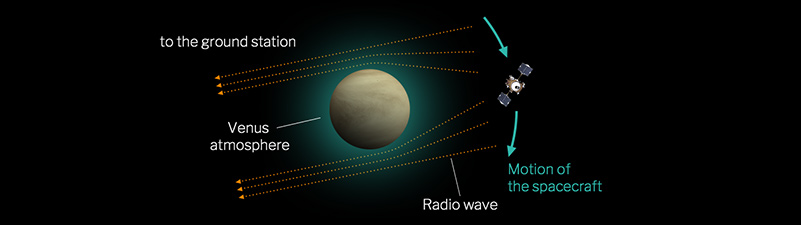
Ultra-stable oscillator (USO)
When Akatsuki is concealed behind Venus as seen from the Earth, the radio waves transmitted by Akatsuki graze Venusian atmosphere and reach the Earth. This causes the received radio wave frequency to change. Analyzing those changes allows us to measure the vertical profiles of temperature and sulphuric acid vapor. The ultra-stable oscillator is a radio wave generator used for that purpose.
PI: Takeshi Imamura (University of Tokyo)
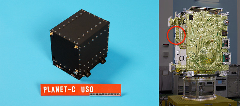
Specification
| Mass | About 2 kg |
|---|---|
| generated and transmitted frequencies and target | USO frequency: 38 MHz Transmission frequency: 8.4 GHz (temperature, sulfuric acid vapor, electron density) |